
Design of a punch and die for small diameter hole punching

Here, punching small diameter holes assumes a size of roughly less than 1.0 mm in diameter. Also, it is assumed that holes of about φ1.0 mm are punched in materials with a plate thickness of around 1.0 mm.
Design of the punch
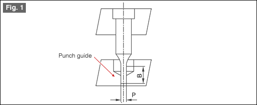
For the sake of preservation, the tip of a punch for hole punching is guided (punch guide) by a stripper as is shown in Fig. 1 thereby preventing the punch from breaking. A guide for the relationship between the dimensions P and B of the punch is a maximum length B less than or equal to 10P (B ≤ 10P). In the case of small diameter punches, the dimension B becomes short and punch guiding becomes difficult.
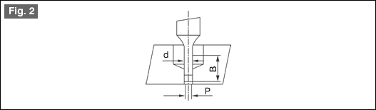
As a preventative measure for this, a two stage punch is used as is shown in Fig. 2. The dimension d above P will be d ≤ P + 2t. The reason for this is to avoid causing any deformations in the hole when the punch is withdrawing from the material. The length of the guide at the tip of the punch is - guide length ≥ punch diameter. Also, the gap between the punch and the stripper should be 0.003 or more at each side. The reason for this is that 0.003 is the minimum gap that does not cause the oil film to break. It may also be good to wrap the side surface of the punch and make it clean.
Design of the die
The key point in die design is to make sure that no chaff gets clogged in the die hole. The reason for this is that the force for pushing down the chaff is quite large and the force for punching the hole becomes considerably large.
See Fig. 3
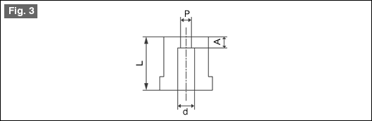
As a countermeasure, make the length of the punch tip (A) as short as possible. Also, it is better to remove the punching chaff after punching each hole. Also, as a rule, the chaff dropping hole (d) should not be made too large with respect to the dimension P. At this time, as the dimension d is being made smaller, at the same time the length (L) of the die should also be made smaller. This is a countermeasure against clogging. The clearance should be made larger than normal. This is for reducing the punching force as much as possible. If the punching of small holes is done at a normal clearance, the shear surface will be drawn out longer. This is due to the fact that the punching chaff has gotten crushed
WHAT WE SPECIALIZING ARE PUNCHES ,DIES,PINS ,BUSHES AND PRECISION ROUND PARTS
1.Standard punches.Punches DIN 9861,Punches ISO 8020,Ejector punches,Shoulder punches,Polit punches,Block punches
2.Punches and Dies as Standard DAYTON / MISUMI / FIBRO
3.Standard Pins,Ejector pins DIN 1530 A/ DIN 1530 AH/ DIN 1530AP Black nitride/ Step Ejector pins. Flat Ejector DIN 1530 F/ Ejector Sleeve DIN 16756
4.Standard Bush DIN 172 / DIN 179 Standard Die Bush ISO 8977 / DIN 9845
5.Carbide punches,pins,bushes
6.Precision parts as per drawings
Hits: 【Print】